
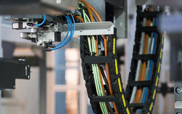
In an automated warehouse, moving cable connections can undergo repeated bending as shuttles, stacker cranes and gantries operate. Where an energy chain (also called a drag chain or cable chain) is used, the cable must withstand the machine’s movement over its intended operating life. Cable suitability is therefore an important consideration at the design stage, not simply another item on the bill of materials.
This guide explains which operating conditions to confirm before selecting energy-chain cables for intralogistics equipment and how LAPP cable families can support different functions. It builds on our intralogistics cable selection for AGVs, AS/RS and conveyors guide and focuses specifically on cabling installed in moving energy chains. Not every warehouse machine uses an energy chain; alternative arrangements include conductor rails, cable-reeling systems and wireless communication, depending on the equipment design.
What should be confirmed before selecting a drag chain cable?
Begin with the movement profile and the cable’s electrical function. Record the following information for each moving axis.
Travel distance. What distance does the moving end travel between its operating limits? Travel distance is not the same as the length of the energy chain or the installed cable.
Speed, acceleration and reversals. A shuttle operating with high acceleration and frequent changes of direction imposes different dynamic demands from a slower axis with intermittent movement.
Self-supporting or sliding energy chain. In a self-supporting (unsupported) arrangement, the upper run spans the permissible distance without continuous support. In a sliding arrangement, the upper run moves along the lower run or a support surface, usually within a guide trough. Each arrangement has different mechanical and operational limits.
Orientation and bending radius. Identify whether the chain is installed horizontally, vertically or on its side, and confirm the available bending radius. The chain radius must not be smaller than the minimum dynamic bending radius specified for the selected cable.
Expected bending cycles and cable function. Estimate how often the axis moves during its intended service life and identify the circuits required, such as power, motor and servo connections, control, encoder feedback, fieldbus or Ethernet. Cable screening and separation must also reflect the electrical requirements.
These parameters should be assessed together. A cable suitable for the required speed may still be unsuitable for the available bending radius, travel distance or expected bending-cycle duty.
How do travel distance, speed and bending cycles affect selection?
Applications with shorter travel distances and lower dynamic loads may permit a less demanding cable performance class. Long-travel systems or axes with high acceleration and frequent reversals generally require cables designed for more demanding continuous-flexing conditions. LAPP’s selection tables compare cable families by travel distance, acceleration, speed, operating temperature and bending-cycle requirements, with bending-radius factors that depend on the application.
Long travel also affects the energy-chain arrangement. When the permissible self-supporting span is exceeded, a sliding arrangement with a guide trough or another appropriately engineered cable-guidance system may be required. Cable selection and chain design should be coordinated: the cable diameters, weights and bending radii influence chain dimensions, while chain loading, support and travel arrangement determine the permissible operating conditions. These choices should be verified with the energy-chain manufacturer.
LAPP offers different cable performance classes for such applications. ÖLFLEX® CHAIN 809 CY is a screened Basic-Line control cable for moderate dynamic requirements. ÖLFLEX® CLASSIC FD 810 is an unscreened Core-Line power and control cable designed for continuous flexing at medium travel distances or increased acceleration. These products should not be treated as directly interchangeable: electrical function, screening, construction and the specific operating limits must all be considered. More demanding applications may require a suitable Extended-Line variant.
What does this look like in an automated warehouse?
Consider an automated storage and retrieval system (AS/RS) with a stacker crane travelling along an aisle and lifting a load carrier on a vertical mast. The horizontal travel axis and vertical lifting axis have different movement profiles and may require different cable-guidance arrangements.
For a horizontal travel axis using an energy chain, the designer confirms the travel distance, speed, acceleration and permissible chain arrangement. A long travel may require a sliding energy chain and guide trough. The vertical lifting axis must be assessed separately: depending on the machine design, cables may run in a vertical energy chain, a cable loop or another suitable guidance system. A freely suspended lifting cable must not be assumed equivalent to an energy-chain cable.
Each connection also has a distinct electrical function. Servo motor connections routed through an energy chain may use a suitable continuously flexing cable such as ÖLFLEX® SERVO FD 796 CP, subject to drive and motor requirements. Control circuits can use an appropriately specified ÖLFLEX® FD cable. For moving industrial Ethernet links, ETHERLINE® FD P Cat.6 is a potential solution and is listed for suitable EtherCAT and EtherNet/IP applications. Where moving equipment instead uses a fieldbus protocol, a compatible UNITRONIC® FD cable (for example, part number 0027857) may be considered, based on both the protocol and mechanical conditions.
The cable families serve different power, control and communication functions, and each must be selected for the actual movement profile. Some machines use alternative power or data-transfer methods, such as conductor rails or wireless systems. These are system-design decisions; this guide addresses cabling where an energy chain has been specified.
Why is a bending-cycle rating alone insufficient?
A statement that a cable is suitable for energy chains, or a published bending-cycle figure, does not establish suitability for every installation. Minimum dynamic bending radius, travel distance, acceleration, speed, temperature and installation method all influence the mechanical demands on the cable.
LAPP’s bending-cycle tables for power and control cables and for data cables provide guidance under defined operating parameters. In particular, the data-cable bending-cycle figures are based on specified test conditions and should not be interpreted as a guarantee of identical service life in a different installation. Final selection should therefore follow the exact cable datasheet and the intended operating profile.
Installation quality matters as much as the published rating. LAPP’s assembly guidelines for cables in energy chains call for twist-free cable installation, adequate clearance, appropriate use of separators and sufficient freedom of movement through the neutral bending zone. Cable fixing arrangements also differ between self-supporting and sliding energy chains. Follow the relevant cable and energy-chain manufacturers’ assembly instructions.
The same selection discipline applies to data cables. An Ethernet cable rated for continuous flexing must still meet the required transmission performance and network interface. Confirm the communication requirements first, as explained in our PROFINET cable selection guide, then verify the cable’s dynamic suitability.
What should be checked before ordering?
Before finalising the cable specification, confirm the following with LAPP technical support and the energy-chain manufacturer:
Operating profile: travel distance, speed, acceleration, reversal frequency, expected bending cycles, operating temperature and installation orientation.
Energy-chain arrangement: self-supporting or sliding design, permissible loading, available bending radius, chain fill, cable clearance, separators and strain-relief provisions.
Cable function: appropriate variants for power, servo, control, fieldbus and Ethernet, including conductor construction, screening and transmission requirements.
Installation conditions: twist-free cable routing, movement in the neutral bending zone, and a guidance method suitable for any long-travel or vertical axis.
Documented compatibility: check the exact product datasheet and LAPP’s relevant selection and assembly tables rather than relying on a general product-family description.
Talk to Our Connectivity Specialists
Reliable connectivity in automated warehouses requires more than choosing a cable described as suitable for continuous flexing. Whether your application involves an AS/RS stacker crane, shuttle or gantry, LAPP technical specialists can help review the movement conditions, electrical requirements and available ÖLFLEX®, UNITRONIC® and ETHERLINE® cable options.
Contact LAPP Southeast Asia through the LAPP SEA enquiry page. Share the travel distance, speed, acceleration, bending-radius constraints, energy-chain configuration, operating environment and the function of each cable.


