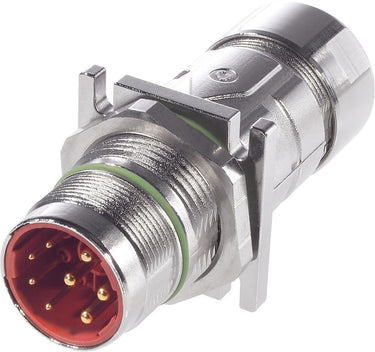

EPIC® POWER LS1 F7 3+PE+4 K 10,5-15,5 (5)
Control cabinet bushing; M 23 power; Pin; Number of contacts: 3+PE+4; Clamping range (min./max.): 10.5mm - 15.5mm
 EPIC® POWER LS1 F7 3+PE+4 K 10,5-15,5 (5)
2,929.67 ฿
/
EPIC® POWER LS1 F7 3+PE+4 K 10,5-15,5 (5)
2,929.67 ฿
/

EPIC® POWER LS1 F7 3+PE+4 K 10,5-15,5 (5)
2,929.67 ฿
/
Payment & Security
Your payment information is processed securely. We do not store credit card details nor have access to your credit card information.
Product characteristics
Certificate
 CE marked
Benefits
High power at smallest installation space, Optimal solution for electric motors, EMC-optimised design, Safety use in field environment by high protection class
Applications
Plant engineering, Servo drives and servo assemblies
Technical Attributes
General Information
| Brand | EPIC® |
| Contacts included |
|
| Product type | Control cabinet bushing |
| Scope of delivery | including contacts |
| Delivery Unit | 5.000 |
| Weight | 0.115 kg |

Electrical Characteristics
| Rated impulse voltage signal contact | 4 kV AC rms / DC according to IEC 61984 to 4 |
| Rated surge voltage power contact | 6 kV AC rms / DC according to IEC 61984 to 3 |
| Rated current signal contact | 7 A according to UL, 7 A according to CSA, 7 A according to IEC |
| Over voltage category | III |
| Rated current power contact | 26 A according to UL, 26 A according to CSA, 26 A according to IEC |
| Rated voltage power contact | 630 V AC rms / DC according to IEC to 3, 600 V AC rms / DC according to UL to 3, 600 V AC rms / DC according to CSA to 3 |
| Rated voltage signal contact | 250 V AC rms / DC according to IEC to 4, 250 V AC rms / DC according to UL to 4, 250 V AC rms / DC according to CSA to 4 |
| Max. contact resistance | 4 |
Product Design
| Min. cable clamping range | 10.5 |
| Total length | 77 |
| Cable gland material | Polyamide |
| Design connector housing | Straight |
| Connector format | M 23 power |
| Cable gland material, short form | PA |
| Max. connectable conductor cross-section of power contacts (mm2) | 4 |
| EMC screening |
|
| Stripping length of the sheathing | 40 |
| Colour | green |
| Housing colour | silver |
| Connectable conductor cross section min. (AWG) | 26 AWG |
| Max. connectable conductor cross-section AWG | 12 AWG |
| Number of contacts | 3+PE+4 |
| Min. connectable conductor cross-section of signal contacts (mm2) | 0.14 |
| Connector diameter | 28.4 |
| Stripping length, signal contact | 6 mm |
| Housing coating | Nickel-plated |
| Contact material | Brass |
| Stripping length, performance contact | 8 mm |
| With protective conductor |
|
| Housing coating, short form | Ni |
| Contact material, short form | CuZn |
| Material contact surface | Gold-plated |
| Seal type | Sealing ring |
| Coded |
|
| Contact insert material, short form | PA |
| PE connection type | Crimp termination |
| Contact variant | Pin |
| Contact coating material, short form | Au |
| Screen contact type | Terminal connection |
| Connector type | Plug |
| Material contact insert | Polyamide |
| Number of PE contacts | 1 |
| Min. connectable conductor cross-section of power contacts (mm2) | 0.5 |
| Conductor connection type | Crimp termination |
| Housing base material | Zinc alloy |
| With thread |
|
| Stripping length of PE connection | 8 |
| Housing base material, short form | Zn |
| Max. connectable conductor cross-section of signal contacts (mm2) | 1 |
| Locking type | Screw lock |
| First make, last break PE contact |
|
| Screen contact |
|
| Number of signal contacts | 4 |
| Max. cable clamping range | 15.5 |
| Sealing material, short form | FKM |
| Sealing material | Fluorinated rubber |
| Number of power contacts | 3 |

Product Characteristics
| Corrosion-resistant |
|
| Operating temperature min. | -25 |
| Operating temperature max. | 125 |
| Min. number of insertion cycles | 500 |
| Operating temperature min. static (no plugging or unplugging) | -40 |
| Impact-resistant |
|
| Pollution degree | 3 |
| Vibration protection |
|
| IP protection class plugged in | IP 68 - 1m (10h) |
| Corrosion-resistant according to | DIN EN 60068-2-60, Ke 4 |
| Halogenfree |
|
Certifications and Standards
| UR recognized |
|
| cUR recognized |
|
| CSA certified |
|
| cUR category control number | CYJV8 |
| UL category control number | CYJV2 |
| Product standard according to IEC | IEC 61984 |
| UR certification | according to UL 2238 (e-file number: E249137) |
| cUR certification | according to CSA C22.2 No. 182.3 (e-file number: E249137) |
| VDE registration number | B25 |
| CE marked |
|
| VDE certified |
|
| EAC certification number | Отказное письмо № 39 |
| EAC-certified | Not required |
Documentation
Downloads
Further Links
Notes
- Photographs and graphics are not to scale and do not represent detailed images of the respective products.
- Unless specified otherwise, the product values shown are rated values at room temperature. You can receive further values, such as tolerances, upon request if they are available and have been released for publication.
Product Family List
All articles from EPIC® POWER LS1 F7
| Article number | Number of contacts | Contacts included | Delivery Unit | Imp cable clamping range min | Min. cable clamping range | Imp cable clamping range max | Max. cable clamping range | Number of power contacts | Number of PE contacts | Min. connectable conductor cross-section of power contacts (mm2) | Number of signal contacts | Max. connectable conductor cross-section of power contacts (mm2) | Min. connectable conductor cross-section of signal contacts (mm2) | Max. connectable conductor cross-section of signal contacts (mm2) |
|---|---|---|---|---|---|---|---|---|---|---|---|---|---|---|
| 73000016 | 3+PE+4 | Yes | 5.000 | 8.5 | 11 | 3 | 1 | 0.5 | 4 | 4 | 0.14 | 1 | ||
| 73000017 | 3+PE+4 | Yes | 5.000 | 10.5 | 15.5 | 3 | 1 | 0.5 | 4 | 4 | 0.14 | 1 | ||
| 73000020 | 5+PE | Yes | 5.000 | 8.5 | 11 | 5 | 1 | 0.5 | 0 | 4 | ||||
| 73000021 | 5+PE | Yes | 5.000 | 10.5 | 15.5 | 5 | 1 | 0.5 | 0 | 4 | ||||
| 73000023 | 5+PE | No | 20.000 | 10.5 | 15.5 | 5 | 1 | 0.5 | 0 | 4 | ||||
| 76143000 | 5+PE | Yes | 5.000 | 7.5 | 15.5 | 5 | 1 | 0.5 | 0 | 4 | ||||
| 76144000 | 3+PE+4 | Yes | 5.000 | 7.5 | 15.5 | 3 | 1 | 0.5 | 4 | 4 | 0.14 | 1 | ||
| 76144510 | 3+PE+4 | No | 20.000 | 7.5 | 15.5 | 3 | 1 | 0.5 | 4 | 4 | 0.14 | 1 |


Lorem Ipsum Dolor
Lorem ipsum dolor sit amet consectetur. Facilisis elementum auctor amet lorem vitae.

Lorem Ipsum Dolor
Lorem ipsum dolor sit amet consectetur. Facilisis elementum auctor amet lorem vitae.

Lorem Ipsum Dolor
Lorem ipsum dolor sit amet consectetur. Facilisis elementum auctor amet lorem vitae.


)